Use the following template to help create your post:
-
State the model of servo you are using.
Robotis Engineer Kit - 2 (Max E2)
-
Add (or create) Tags to your post with the specific model of your product.
Engineer Kit 2, Raspberry Pi and Matlab programming
-
Describe your control environment. This includes the controller or interface, computer and OS, and any power source you are using
Windows 10 PC with matlab 2022a interested in controlling the Max E2 from matlab through the CM-550 o through the RPi
-
Specify the operating mode you are using, for applicable models.
NA
-
Specify and link any manuals or resources you have used related to your inquiry.
Python Online Workbook and support Email.
-
Include pictures if possible. This can help our members see how wires are connected, how hardware is installed, or to identify other possible issues.
I am working with a Robotis Engineer Kit 2 assembled as MAX E2. I want to control it from matlab since I programmed the inverse kinematics and many other interest functions on it. I followed the examples of the Python Workbook and I can code the robot in python from R+ Task 3.0 but I don’t know how can I establish communication with the PC and the robot.
The support mail recommended to use the U2D2 and the Dynamixel SDK that works with matlab and I am considering it, however I don’t want to lose communication with the CM-550 as it has the IMU registers onto it.
Alternatively I would like to know if I can program the rapsberry Pi Zero W directly to stablish connection with matlab and control the robot this way.
If anyone can give me some advice on how to proceed and or any tutorial or repository to review I would be very grateful. Thanks for reading up to this point and have a nice day.
3 Likes
@roboteer as the resident expert on the ROBOTIS Engineer kit, would you be able to offer some advice to @DavidYR?
3 Likes
What it comes to my mind is as follows.
-
RPI + U2D2 with SDK Tutorial : DYNAMIXEL Quick Start Guide for Raspberry Pi (C language) - YouTube
-
Matlab with SDK : DYNAMIXEL Quick Start Guide in MATLAB on Linux - YouTube
-
If you would like to get sensor state from CM-550, see PYCM IMU module (Micro Python).
Combining given information, I think you can start Matlab with Engineer Kit2.
SBC - Implementing Micro Python and DYNAMIXEL SDK
U2D2 - UART to TTL converter
CM-550 - Sensor States
Hope this helpful,
1 Like
@DavidYR
Unfortunately, I have never used Matlab with ROBOTIS robots, so I cannot be of direct assistance for you with this specific project. But I have developed projects using Python and C++ with the ENGINEER Kits using a combination of DXL-SDK (Python, C++) on the RPi side, and TASK/MOTION/microPython tools on the CM-550 side, and here are some aspects that may be relevant to your project:
-
From the ROBOTIS Dynamixel Network viewpoint (i.e., DXL SDK), the CM-550 is a special DXL with the ID=200. So, you should be able to access the IMU registers 102 through 118 by reading in 2 bytes via a Read command from the MATLAB DXL SDK. As I don’t use MATLAB, it would be great if you can check out this item yourself (I would like to know the result too  ). The Control Table for the CM-550 is accessible here CM-550
-
I have used the MAX-E2 with the RPi4B and posted the results on YouTube:
RPi4B + MAX E2 Integration: Mechanical Aspects - YouTube
RPi4B + MAX E2 Integration: Computing Aspects - YouTube
-
I have used the RPi0 2W with a OpenCM-904 based robot using XL-430 servos from the ENGINEER Kits:
Using RPi0-2W with OpenCM904 (Part 1) - YouTube
Using RPi0-2W with OpenCM904 (Part 2) - YouTube
Hope that these informational items are useful to your project.
2 Likes
Thanks for the information, I will buy the U2D2 and try working with the DXL SDK and Matlab. On the other hand I just started to read the Projects guide Vol. 2 for better understanding how to use with the CM 550 controller with an external controller with bidirectional communication. I will tell you how everything proceeds when I advance with the project. Thank you again and have a nice day.
2 Likes
This seems to be very useful information. Let’s put this post as recommended resource !
Please continue to update your ongoing project and share your experience on this community page.
2 Likes
The Remocon packet is described in detail in the Engineer Book Vol. 1, but the construction of the Remocon packet is also accessible here (RC-100A/100B).
1 Like
Talking with a partner here, he recommended me to try using serial comunication for working with Matlab. Would that be possible? disconnecting from roboplus and using the serial bluetooth comunication to send and receive information to/from the robot. I can read messages from the robot but don’t know how to receive them. I tried with the packages Serial and machine uart but they don’t seem to installed which takes me to another question. Can I install python packages onto the robot? If yes, how?
1 Like
Following this idea and using the functions input() to read and print() to write onto the serial port now I have bidirectional communication. A little issue to be considered is that the default terminator in matlab is not CR but LF so its necesary to set that configuration in the serial object for it to work. I will work with this for a while and see how this works.
1 Like
@DavidYR
Can you please clarify which software are you using on the CM-550? TASK or microPython (pycm)? Either software can only receive and extract data from a Remocon Packet. They are not setup to receive and use just plain ASCII strings. However, they can send plain ASCII strings via PRINT and PRINTLN functions to the RPi. Also you cannot install Standard Python on the CM-550.
On the RPi, I am assuming that you are using MATLAB, and what do you want to send out from the RPi to the CM-550? and what do you expect back? Are you using DXL-SDK to send your Instruction packets? DXL packets are not the same as Remocon packets, unfortunately. Also if you are sending DXL packets to the CM-550, it will set itself into MANAGE mode and suspend both TASK and microPython functionalities. All this is explained in Vol. 1 but not repeated in Vol. 2. You can read about this issue at this web link also:
Also if you had purchased Vol. 2, the instruction for getting the associated source codes is accessible at the bottom of this web page (https://www.cntrobotics.com/engineer)
1 Like
I am using microPython. Here, with the function ‘console(BLE)’ I can sent plain ASCII strings into the serial port using the print() function.
print('Hello World')
sends the string into the serial port and I can read that string from matlab using:
device = serialport("COM4",57600)
configureTerminator(device,"CR/LF",'CR')
reading = readline(device)
This way I can send any information that I want information to Matlab through the serial port.
On the other hand, for writing we noted that the function input() allows to read information from the serial port. Using this, I can send target positions to the motors:
arrived = input()
q = int(arrived)
dxl[i].goal_position(q)
This is how we got bidirectional communication from matlab and the robot using the USB Bluetooth dongle. The lost of some packages distorts some messages so I’m figuring how to guarantee the information flow but it seems promising.
1 Like
@DavidYR
Great! I have learned something new today: how Matlab does “Serial” with CM-550. Also thanks for sharing about pycm’s Function input(). The Robotis e-manual sure did not mention anything about that function (see CM-550 MicroPython API).
It is OK to start with console(BLE) to try things out, but you will be restricted to 57600 bps and occasional corrupted packets will happen as you already experienced.
You eventually need to look at the Control Table of the CM-550 at this link CM-550
and read up about Address 35 (Task Print Port) and you can see that you can also set it to UART or USB. “Task Print Port” maps to function console() in MicroPython. You will need the U2D2 or LN-101 if you want to use UART, but you can just use a plain USB cable to connect between your PC COM port and the microUSB Port on the CM-550 for now. So far I had used the USB and UART ports this way up to 115.2 Kbps (see Sections 6.2 and 7.4 of Vol. 2), because I did not need a higher baud rate, but maybe you do?
One last thing, when you shift to the RPi, don’t forget the issue of USB Latency Timer on Linux, so read up on Section B.9 of Vol. 2 also.
2 Likes
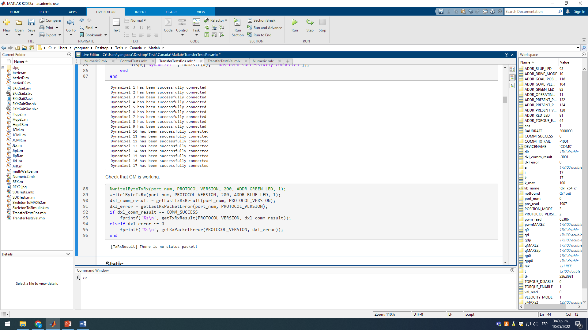
Hello again, I restarted working with the real robot with the U2D2 and the Matlab SDK this week and connected properly to the Dynamixel network. However when I try to read the IMU information using instructions as:
IMU_roll = read4ByteTxRx(port_num, PROTOCOL_VERSION, 200, 102);
it does not work. Also when I use the Dynamixel Wizard, it detects all the motors but it does not seem to be detecting the CM550 In the address 200 as expected. Is there any suggestion to fix that?
Thank you in advance.
1 Like
-
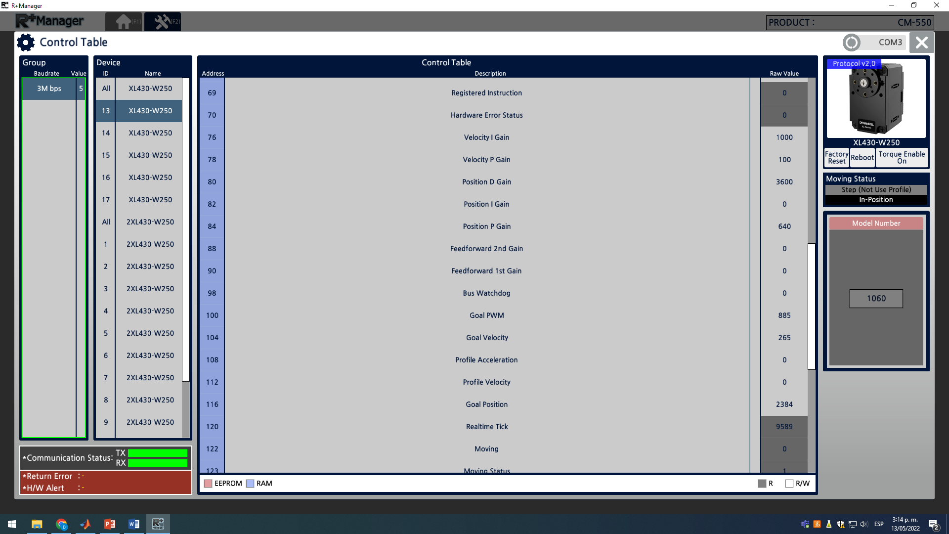
Dynamixel Wizard does not support CM550. You should be able to detect the controller by R+Manager 2.0
-
The Addr 102 (Roll of IMU orientation) has 2 byte access. You should use read2ByteTxRx
-
Packet Window
-
Implementing DYNAMIXEL SDK (Ubuntu 16.04, C++)
-
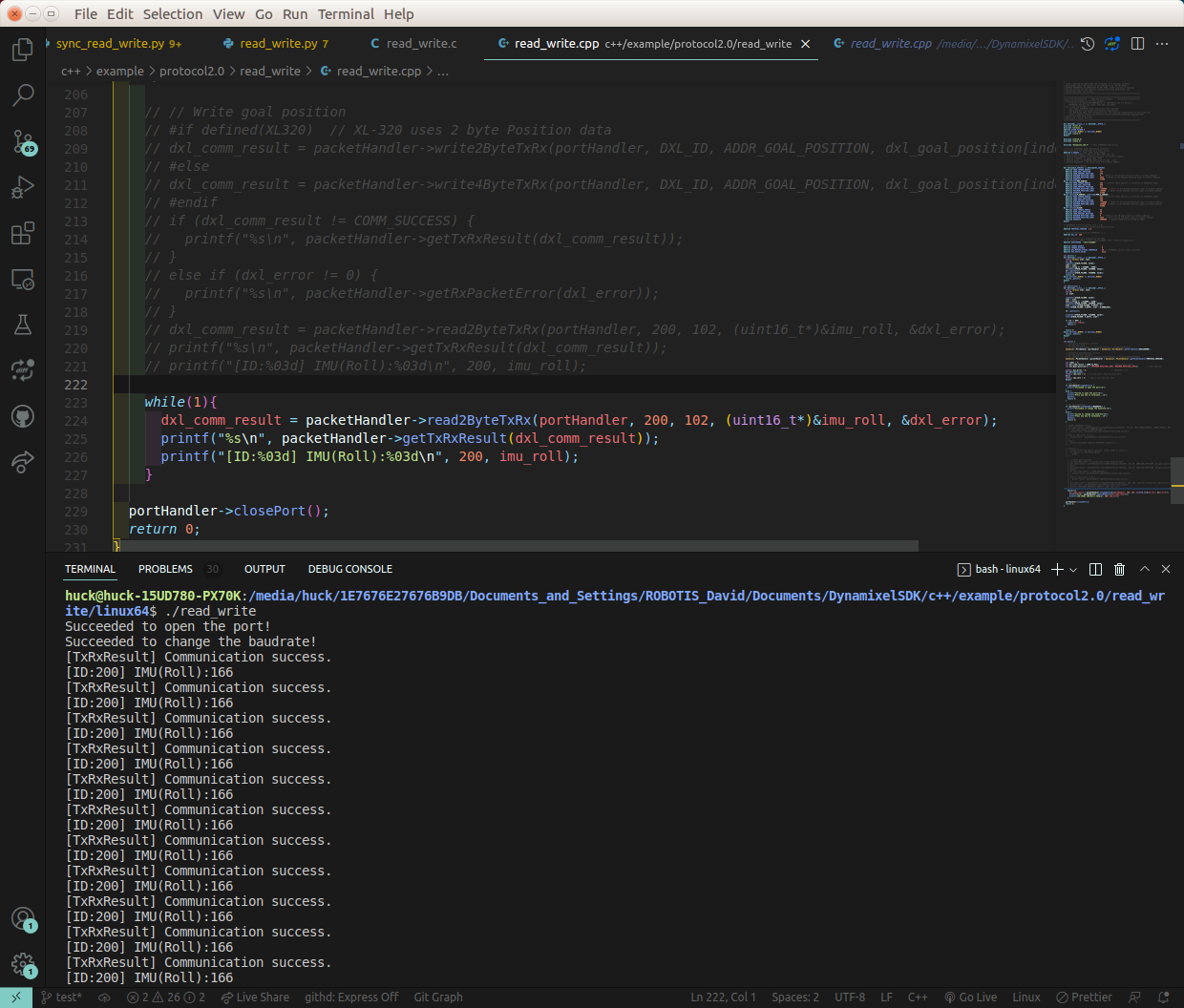
Brief Code Example
   dxl_comm_result = packetHandler->read2ByteTxRx(portHandler, 200, 102, (uint16_t*)&imu_roll, &dxl_error);
   printf("%s\n", packetHandler->getTxRxResult(dxl_comm_result));
   printf("[ID:%03d] IMU(Roll):%03d\n", 200, imu_roll);
-
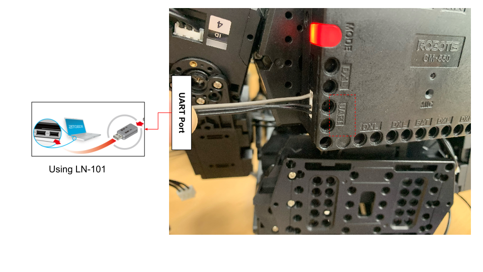
H/W Setup
DYNAMIXEL SDK has connected to CM-550 through the UART port using LN-101. (USB is also okay. In this case, ttyACM# (Linux) should be defined for opening a port)
2 Likes
@DavidYR
There is also another “big-picture” issue that you need to be aware of and it has to do with how you are going to move the MAX-E2 i.e., to make it walk or move its arms, and the way the firmware on the CM-550 works when an DXL Instruction Packet is sent to it via the DXL SDK (like the one Yogurt_Man had just shown you). I already mentioned this issue in one of my previous posts:
-
Previously, you mentioned that you plan to use MicroPython on the CM-550 also? Is it so that you can use the MOTION Data structure created by the TASK tool? If this is the plan, then you need to be aware that as soon as the CM-550 receives a DXL Instruction Packet such as the one reading the IMU Roll out of DXL(200). The CM-550 will put itself into the “MANAGE” mode (like when you use MANAGER from the PC to connect to it), and it will disable (but not erase) its TASK, MicroPython and Motion features. Consequently, you will have to figure out another way to move the robot and it will take more work because you will have to put all the XL-430s into Time Control mode and convert the MTN3 data structure into custom Matlab arrays. Please read Sections 5.2 and 5.5 of my Vol. 2 for a C++ solution to give you some ideas of the work needed for MatLab.
-
If you prefer to use the functionalities of TASK, MicroPython and MOTION for your robot’s MOTION, then you will need to send the IMU data via a Remocon packet and not via a DXL packet. This is shown in Chapter 3 (i.e., Vol 1) with the CM-550 running on MicroPython and the PC running on either Python or C++.
In short, at run time the CM-550 can send and receive Remocon packets and still keeps its TASK, MicroPython, and MOTION functionalities, but as soon as it receives a DXL Instruction Packet, it will “dumb” itself down to another DXL like the XL-430s.
2 Likes
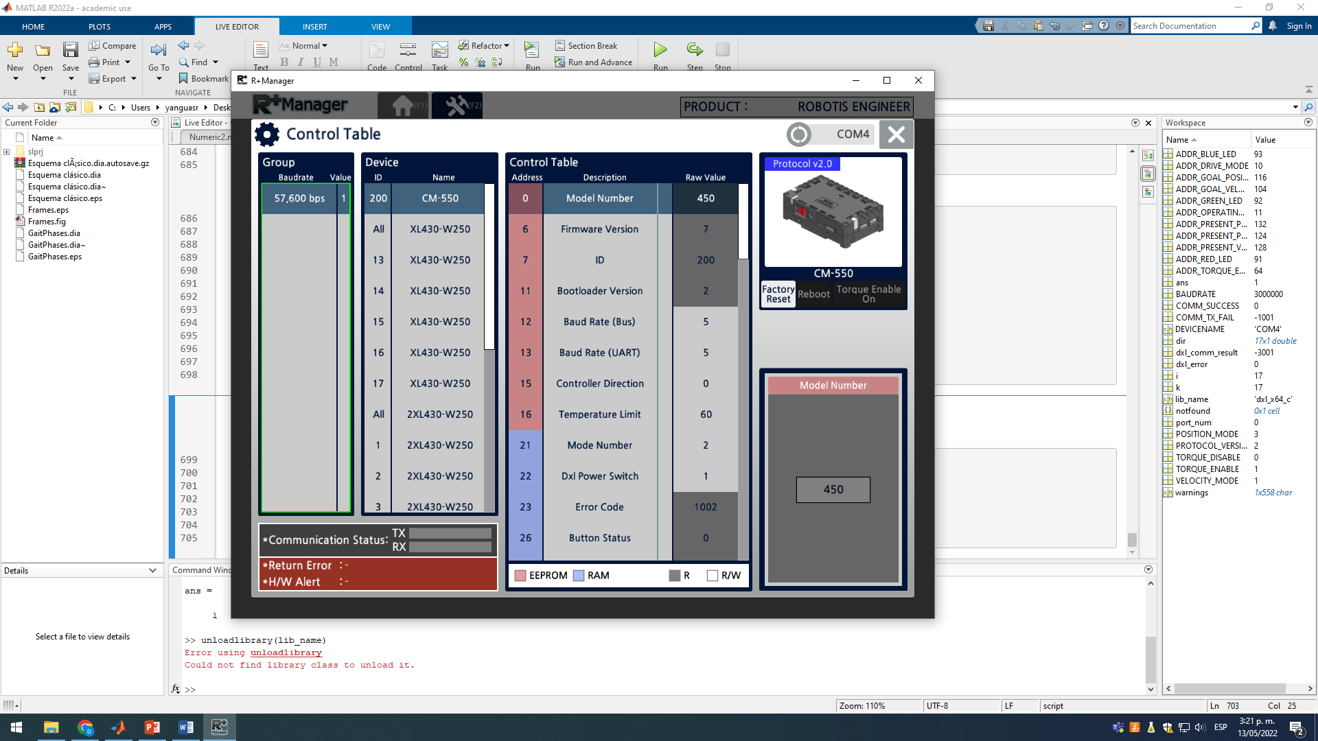
I installed the R+ Manager 2 and the CM-550 does not appear in the list when I connect the robot thorough the U2D2.
But everything appears when I connect the robot through the USB dongle.
On the other hand, when I connect from Matlab with the U2D2 and the SDK, I can reach all the robots but no the CM-550 (I already fixed the reading function to be read1ByteTxRx read2BytesTxRx, read4BytesTxRx to the appropriate one according to the registry size). I am still unable to reach any registry of the CM-550 for reading or for writing:
Just to test, I to connected from Matlab to the robot through the dongle and the SDK (limited to 57k6 baud/s) and I was able to reach everything but way too slow (about 0.3 Hz compared to the almost 10 Hz obtained when connected with the U2D2 at 3M baud/s ) and losing some packages in the process.
With respect to HW setup, I connected the robot and the U2D2 through one of the free TTL ports in one of the ankle servos (I wanted to connect to the UART port of the CM-550 but the UART cable was not included with the kit and it would not be good to place a buy order just for this).
With my current setup I was able to start trying some ideas but I really need to access the sensors information to keep advancing.
It is very interesting the way you used MANAGER via U2D2, I am assuming that you are doing this via one of the XL-430 connections of the robot then (I am going to check this out myself too - I am intrigued). I had always used MANAGER via a plain USB cable from the PC to the microUSB port on the CM-550, or from an LN-101 on the PC to the UART Port of the CM-550 (this is also a wired connection), or through the USB BT-410 dongle (i.e. via Bluetooth to the BLE module on CM-550).
Regarding using the USB Dongle, i.e. the BLE on the CM-550, in Section 6.2.2 of Vol. 2, I also found that using the BLE receiver WILL FORCE the other two COM Ports (UART & USB) down to a baud rate of 57.6 Kbps (I think it’s because of the way the CM-550 firmware is written by ROBOTIS right now), and you already found that out too. For your needs (i.e. high baud rates) do not use/include BLE Communications - use only the USB or UART.
If you do not have the UART cable (i.e. the LN-101), you can connect your PC (i.e., Matlab) via a plain USB cable from the PC into the micro-USB Port of the CM-550 (i.e. via a Windows COM port). For now, I would suggest that you try a similar code to the one suggested by Yogurt_Man to see if you can use Matlab/PC to read the IMU sensor? If this works out as shown by Yogurt_Man, then can you add some more Matlab code just to move one or two XL-430s? This way at least we will know whether you can access the IMU and the XL-430s at the same time in Matlab using only the USB port on the CM-550? I am going to try to do the same thing with Visual Studio 2019 and C++ on my end to see if I can do read the IMU and move a few servos at the same time or not - using only 1 COM port. So far in my projects shown in Vol. 2, I always used ONE COM Port to control the servos via U2D2, and then a second COM port to read sensors and other data from the CM-550 via its USB or UART Port (see Fig. 7.3 in Vol. 2). I’ll let you know in a few days. 
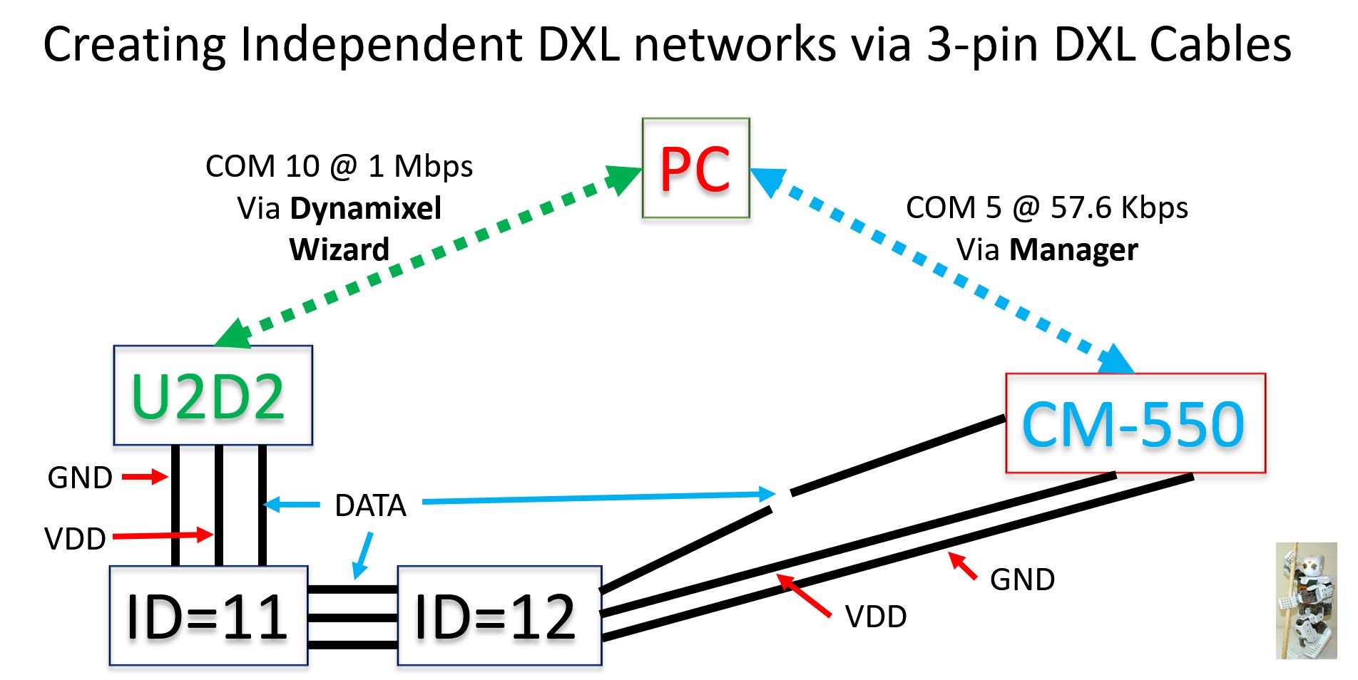
I think that I got things figured out sooner that I thought. It involves the “Independent Dynamixel Networks” idea/approach explained in Sections 4.5, 5.5.2, 6.3.1 and 7.1 of Vol. 2.
For this posting, my “model” setup uses a CM-550 powering one 2XL-430 (ID=11 and 12) in the usual way, except that the DATA line of the 3-pin DXL cable that goes from the CM-550 to the 2XL-430 is CUT OFF (see picture below)
From the PC, I used a plain USB cable to connect it to the CM-550’s USB Port (COM5). Also from the PC, I used another plain USB cable to connect it to my U2D2 (COM10) which is also connected to the 2XL-430 with an INTACT 3-PIN cable. Essentially, as far as the PC is concerned, it is talking to TWO DXL Networks: the first one containing “all” the XL-430s (of the robot), the second one has only 1 DXL (ID=200) which is the CM-550.
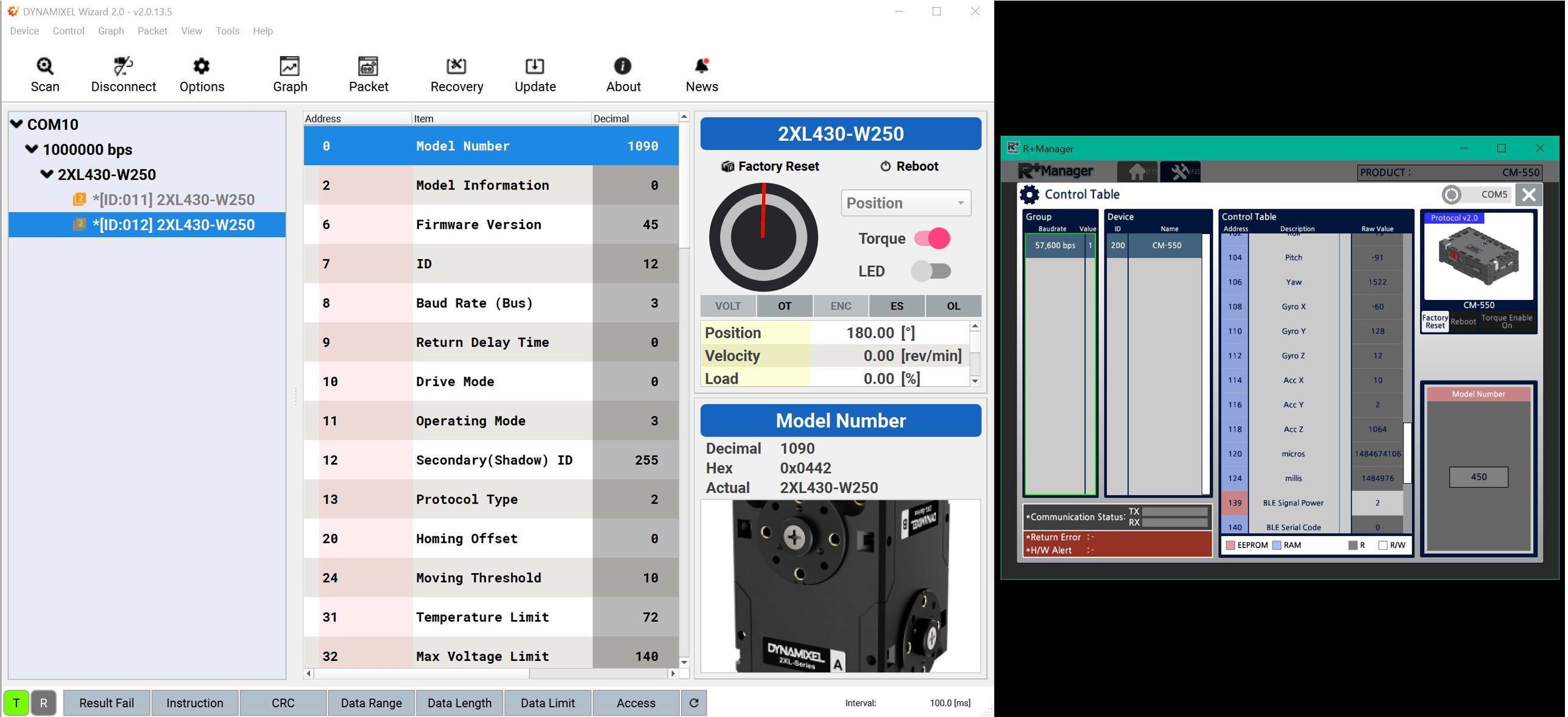
The next picture shows that I can now use Dynamixel Wizard and Manager at the same time on my PC:
Please note that the DXL Wizard (U2D2) runs at 1 Mbps, while the Manager tool can only run at 57.6 Kbps. This could be just the way ROBOTIS designed the Manager tool, because when I used the RPi4B with the USB Port of the CM-550, I could go to 115.2 Kbps (see Fig. 7.3 in my Vol. 2).
If you don’t like “cutting wire”, just set up two separate 12 V power supplies: one to power all the servos, and the other to power just the CM-550 and any other sensor that you may want to attach to the CM-550.
As a final note, this solution pretty much forces you to use the XL-430s in Time Control mode and you’ll need to create your own Motion Data as Matlab arrays (lots of work!), as the CM-550 no longer “sees” the XL-430s!
1 Like