Any experience about OpenCM 9.04 with RC100-B for wireless communication

@Yogurt_Man
Your suggestion does work!
But as writeRaw() is the same as Serial.write() which can only send one byte at a time, I used a FOR loop to send out all 6 bytes of the Remocon packet each time in the TX code. In my test, I used two OpenCM_904s connected together via a pair of Master/Slave BT-210. Both are also connected to a single PC for Serial Monitors via USB cables.

Below is a picture showing both TX and RX codes + their respective “Serial Monitor” screens - please note the 31 ms delay between TX and RX print outs.

1 Like

Good news you dont have to get back the OpenCM IDE.

Hi, thank you very much for sharing your experience about this. It really helps a lot! I will look in detail at these documents and tutorials.

Best regards,
Zicong

1 Like

Hi, thanks for sharing. I really learned a lot from your experience!

1 Like

don’t worry. thanks for your sharing and kind help! :smile:

1 Like

Hi @Yogurt_Man @roboteer Sorry for my coming back so late. Just have time to start the wireless communication with collected stuff. Thanks a lot for your previous reply. I got benefited a lot from them!
However, I didn’t find any document providing the information that how to map sent data to real commands in motor control.
For example, If I would like to press button 1 to send the command ask the motor with ID=1 to rotate clockwise at an angle of 30 deg. How can I do it? Are there any documents I missed?
Or the operation is the same with Dynamixel2Arduino coding? like, dxl.setGoalPosition(ID, deg, UNIT_DEGREE);
Looking forward to your reply!

First, assuming that you are using your MX-64AR in Position Control mode.
Also, assuming that you are staying with the Physical RC-100B, then you are restricted to the 10 RC Buttons UDLR123456, but you can combine “multiple buttons” (i.e., push on more than 1 button at a time). For example, Button “1” when used means that you want to move ID=1, and you can combine it with “U” to mean that you want to increase its Present/Goal Position by 30 degrees, and when “1” is combined with “D” it means to decrease its Goal Position by 30 degrees. This procedure can be implemented using an IF-ELSE-IF structure in Arduino to take care of each considered “buttons combination”. Of course, for each “button-use” case you have to create your own Arduino code to do the actual modification of the designated servo Goal Position within that IF-ELSE-IF structure. How many MX-64 servos do you plan to use? Up to 6 servos can be served easily with this approach. You can also see that this type of “solution” is limited if you have more sophisticated needs.

The Remocon Data is actually 16 bits long
(RC-100A/100B). And you can manipulate these bits to suit your purpose and this video can provide you with some ideas Dual Robots Control with BT-210s and Python - YouTube, if you are willing and able to program some Python or C/C++ codes to access the BT-410 or BT-210 via your laptop or SBC. That video was made for a CM-550 (the Engineer kit) but this approach is also applicable to the OpenCM-904 as the Remocon packet is “standardized” across all Robotis CM-type controllers and the details are provided in this book too (https://www.amazon.com/Projects-Guide-ROBOTIS-ENGINEER-1-ebook/dp/B08KGHQZGP).
Unfortunately, to date, I have not made any similar video or project for the OpenCM-904 using Arduino.

2 Likes

Hi @roboteer. I spend much time trying to understand this and searched some related materials online.
Actually, the first paragraph has been already achieved before asking this question. The motors are in position control and connections between OpenCmM and the master controller have been built via paired BT410 modules. And by pressing the button on RT100, data can be sent to the OpenCM controller yet, which can be seen in the serial monitor.
The main problem is how to send a command to the controller and make it understood by the motor? If my understanding is correct, my previous Dynamixel2Arduino can not be used here. Should I transfer the code into Dynamixel SDK format?

Also, I tried the RC-100.ino example you mentioned. I modified the ID and control mode correspondingly but it didn’t work. Could you please tell me how can I make this example work on my setup?

Sorry for so many questions, thanks a lot for your kind help here.

Here are some figures that might be helpful.

  1. setup

  2. arduino serial monitor

  3. motor setup (ID and control mode)

First, let’s clarify one important point that is “confusing” to me:
Your “text” description says that that you are wanting to use the MX-64s in Position Control mode (i.e., you want your MX-64 to hold a Servo Position that you can control with the RC-100B Controller, i.e. Goal Position values increasing or decreasing between 0 and 4095?), but the Dynamixel Wizard screen says that you are using the MX-64s in Velocity Control mode (see Address 11) - meaning that you want the MX-64 to continuously turn CW or CCW and you want to control this Amplitude of this Continuous Turn Velocity with the RC-100B along with the Turn Direction CW or CCW also?.

So, please clarify your actual needs first, before I can help further.

Hi, sorry for the confusion caused. My final aim is to transfer my current code (control dynamixel motors using position control mode, based on Dynamixel2Arduino) into remote control mode. The main problem that needs to be solved is how to send specific commands with BT410 and RT100. Now I can build the connection between the OpenCM controller and RT100 (reference the second Figure) and send data between them. But I don’t know how to send the command to actuate the motors. So I modified motor configuration (ID and control mode) based on the RT100.ino example, trying to figure out how to make the code work. I think this is helpful to write my own code of position control in this way.
Hope my explanation helps.

As I do not have MX-64s, the following Arduino sketch was made for 2XL-430 with IDs set to 11 and 12 (see details in Dynamixel Palooza with OpenCM-9.04/C + 485-EXP (using MANAGER/TASK and ARDUINO) - #3 by roboteer - Community - ROBOTIS ).

Also, they are set up to use 1 Mbps via Dynamixel Wizard before running this code. Please adjust this code to suit your setup and run it. It should work OK. If not let me know.

#include <Dynamixel2Arduino.h>

#define DXL_SERIAL_3 Serial3 //Serial3 is for DXL Port going to 485-EXP Board
#define DEBUG_SERIAL Serial
const uint8_t DXL_DIR_PIN_3 = 22; //“22” is DIR_PIN for 485-EXP Board
Dynamixel2Arduino dxl_3(DXL_SERIAL_3, DXL_DIR_PIN_3);

//This namespace is required to use Control table item names
using namespace ControlTableItem;

void setup() {
// put your setup code here, to run once:
int8_t found_dynamixel = 0;
// Use UART port of DYNAMIXEL Shield to debug.
DEBUG_SERIAL.begin(115200); //set debugging port baudrate to 115200bps
while(!DEBUG_SERIAL); //Wait until the serial port is opened

dxl_3.begin(1000000); // need to match with DXLs baud rate used via Dynamixel Wizard

int8_t protocol = 2;
dxl_3.setPortProtocolVersion((float)protocol);
DEBUG_SERIAL.println("### SCANNING 485-EXP BOARD ");
DEBUG_SERIAL.print("SCAN PROTOCOL ");
DEBUG_SERIAL.println(protocol);
for(int id = 0; id < DXL_BROADCAST_ID; id++) {
//iterate until all ID in each baudrate is scanned.
if(dxl_3.ping(id)) {
DEBUG_SERIAL.print("ID : “);
DEBUG_SERIAL.print(id);
DEBUG_SERIAL.print(”, Model Number: ");
DEBUG_SERIAL.println(dxl_3.getModelNumber(id));
found_dynamixel++;
if (dxl_3.torqueOff(id))
DEBUG_SERIAL.println(“DYNAMIXEL Torque OFF”);
else
DEBUG_SERIAL.println(“Error: Torque OFF failed”);
if (dxl_3.setOperatingMode(id, (float) OP_POSITION)) // Position Control mode
DEBUG_SERIAL.println(“Position Control mode OK”);
else
DEBUG_SERIAL.println(“Error: Position Control mode failed”);
if (dxl_3.torqueOn(id))
DEBUG_SERIAL.println(“DYNAMIXEL Torque ON”);
else
DEBUG_SERIAL.println(“Error: Torque ON failed”);
}
}

DEBUG_SERIAL.print(“Total “);
DEBUG_SERIAL.print(found_dynamixel);
DEBUG_SERIAL.println(” DYNAMIXEL(s) found!”);
}

void loop() {
// put your main code here, to run repeatedly:
// Moving 2XL-430 on 485-EXP Board - ID=11 and 12
int8_t protocol = 2; // do all DXL with Protocol 2 next
dxl_3.setPortProtocolVersion((float)protocol);
dxl_3.setGoalPosition(12, 1024); // adjust DXL IDs as needed
dxl_3.setGoalPosition(11, 1024);
delay(1000);
dxl_3.setGoalPosition(12, 3072);
dxl_3.setGoalPosition(11, 3072);
}

If this sketch works OK, I’ll work on incorporating the RC-100 protocol next.

1 Like

First of all.

Can you ping your DYNAMIXEL?

When I briefly got throguh the basic code (RC-100.ino). It should comm at 1M bps which is different from the default setup of MX-##(2.0) series

Check if your DYNAMIXEL setup is really corresponding to the code in use.

  • To check the connected baudrates, use scan_dynamixel.ino which would return scanning result at specific bps, protocol, ID
1 Like

Update 5/5/2022
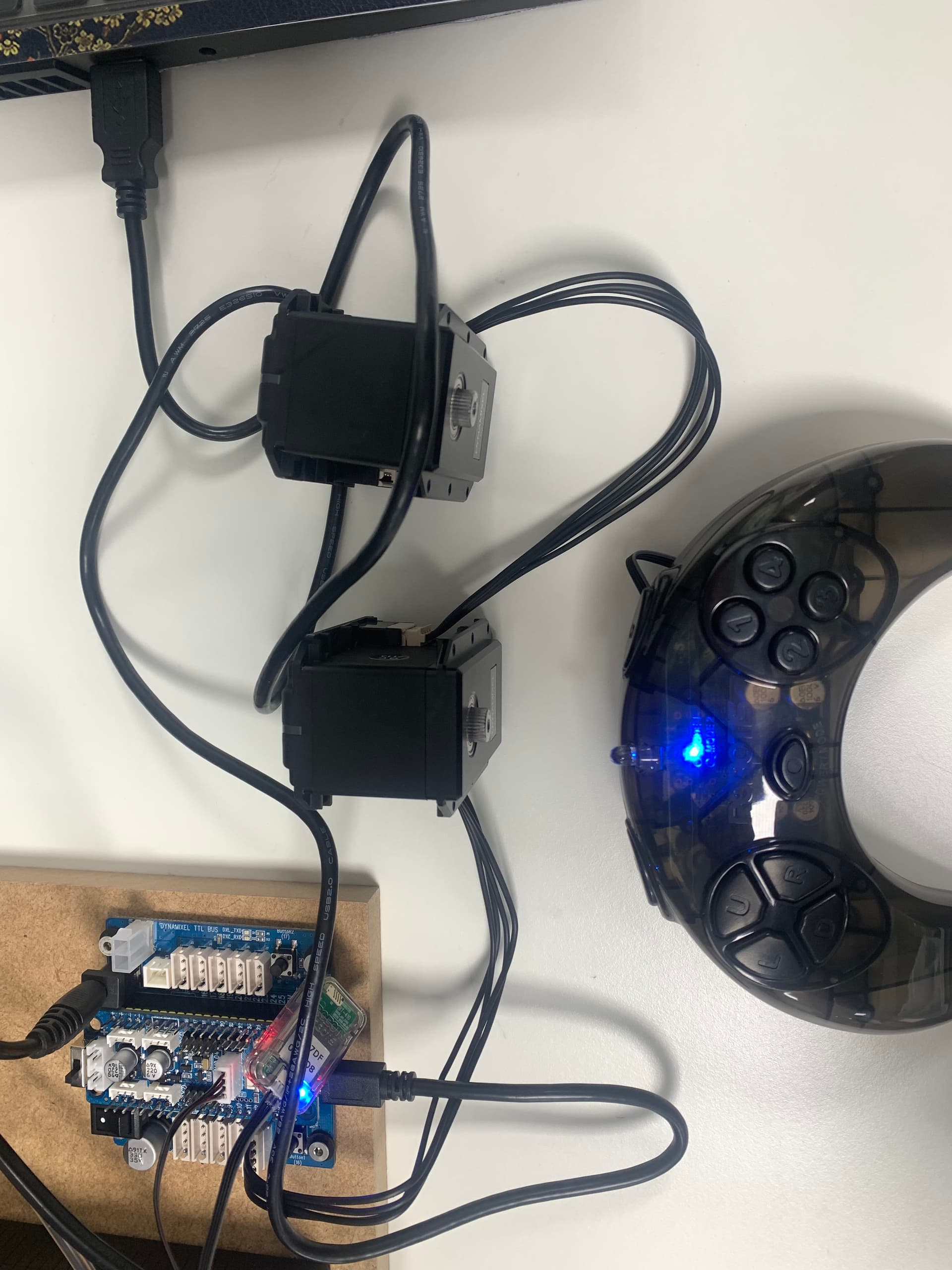
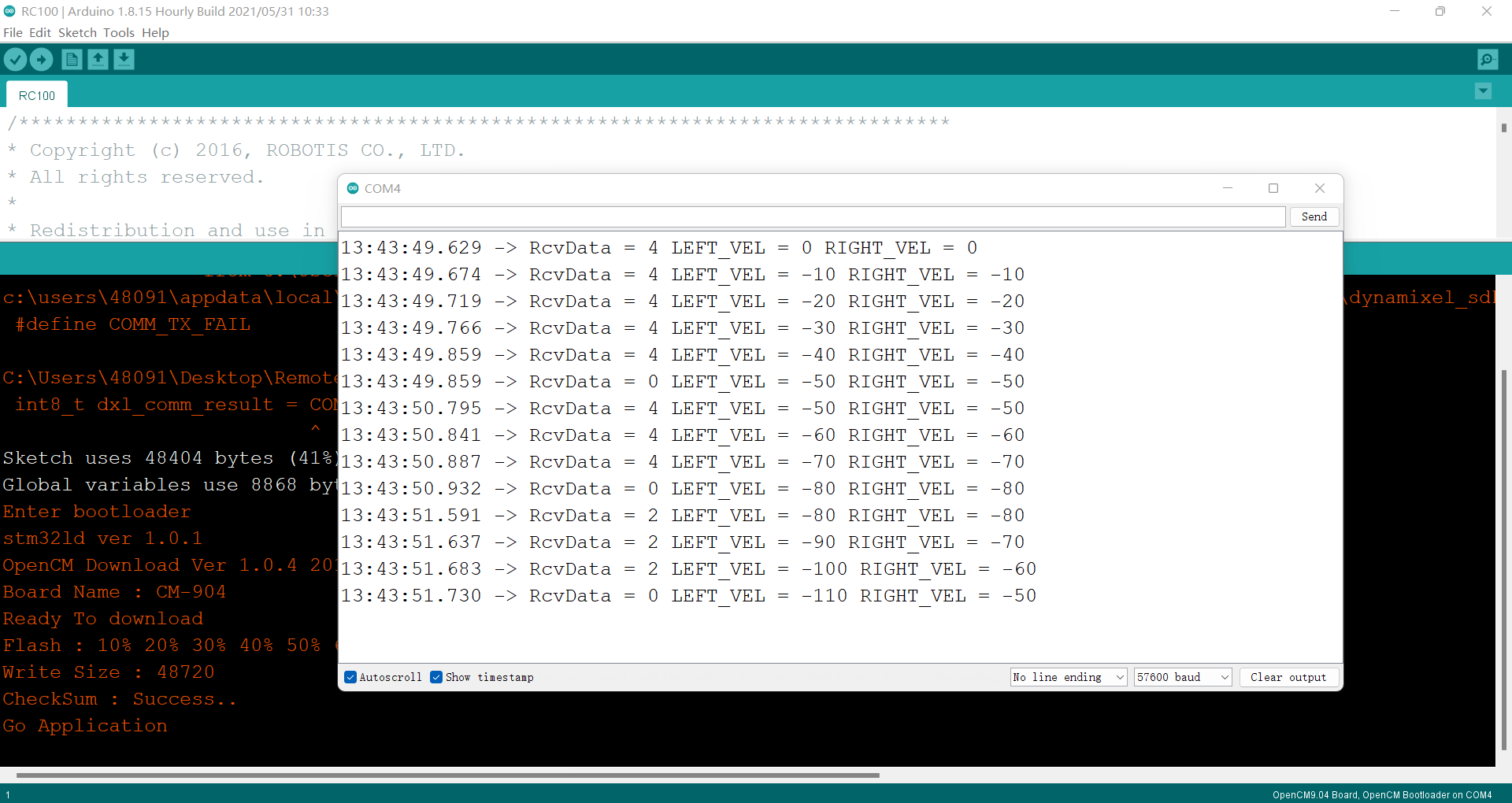
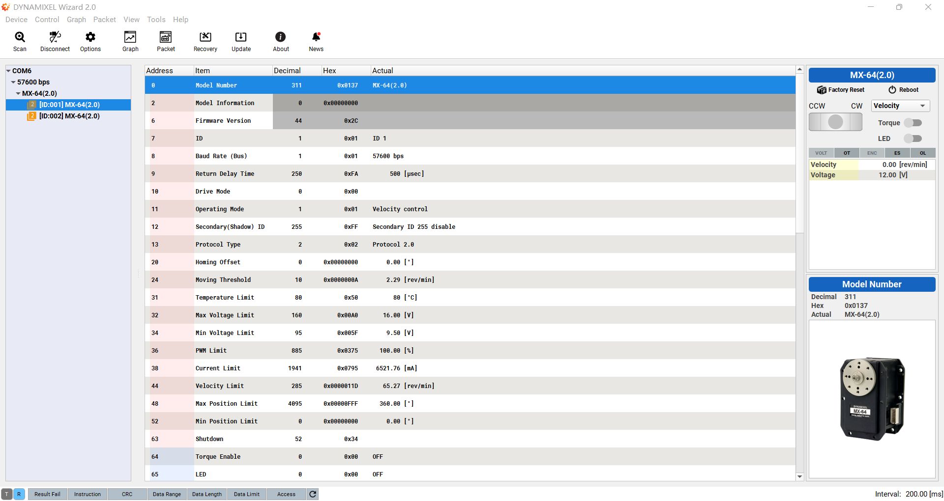
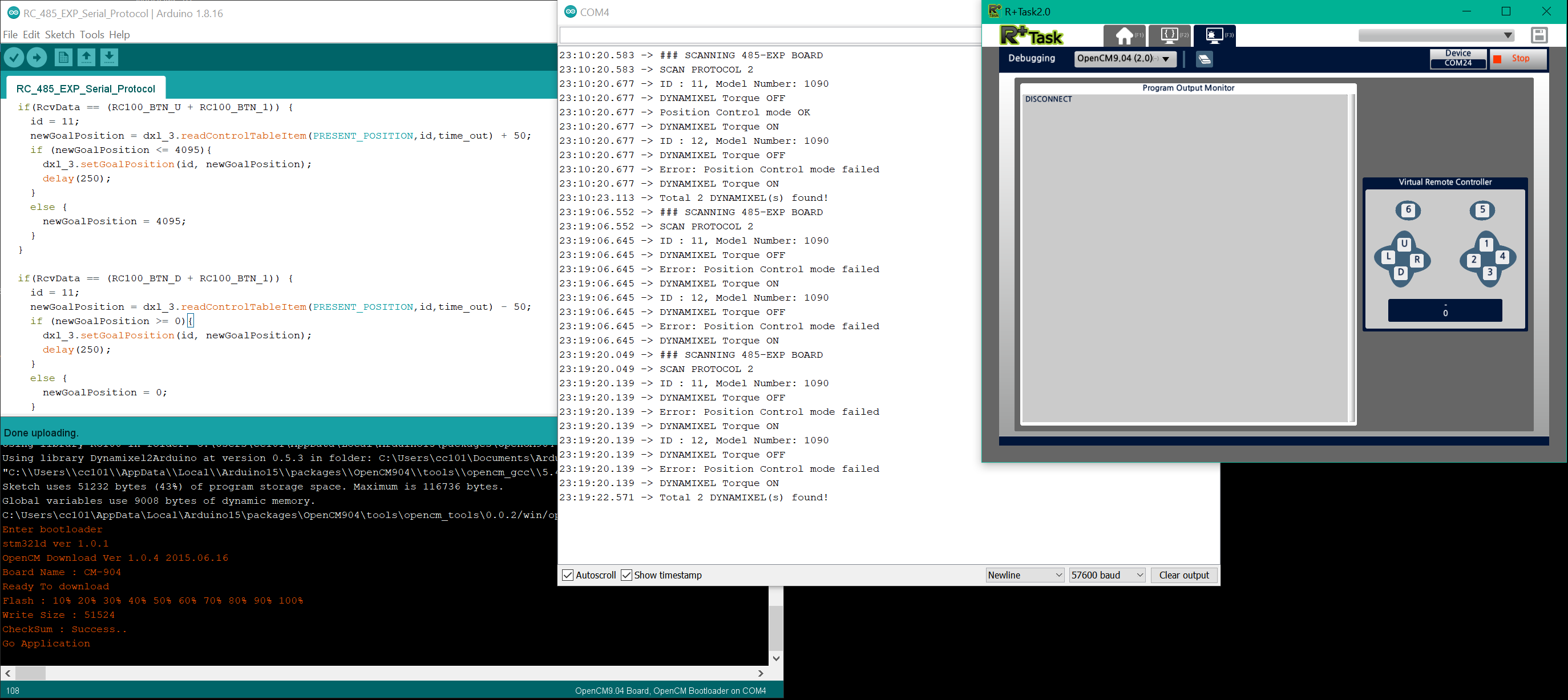
Success! I have found a solution for a 2XL-430 (ID=11 and 12) hooked up on 485-EXP and powered at 12V, while the OpenCM-904/C is separately powered at 7.4V. I am using a USB Cable (COM4) to download the sketch “RC_485_EXP_Serial_Protocol.ino” listed below from ARDUINO 1.8.16 on the PC (Windows 10). I am also using a USB BT-410 Dongle on the PC (COM24) and on the OpenCM-904/C a BT-410 Receiver connected to its 4-pin UART Port (i.e. Serial2). I also use the Debugging Tool on TASK V.2 to act as a Virtual RC-100 Controller (see screen capture below):

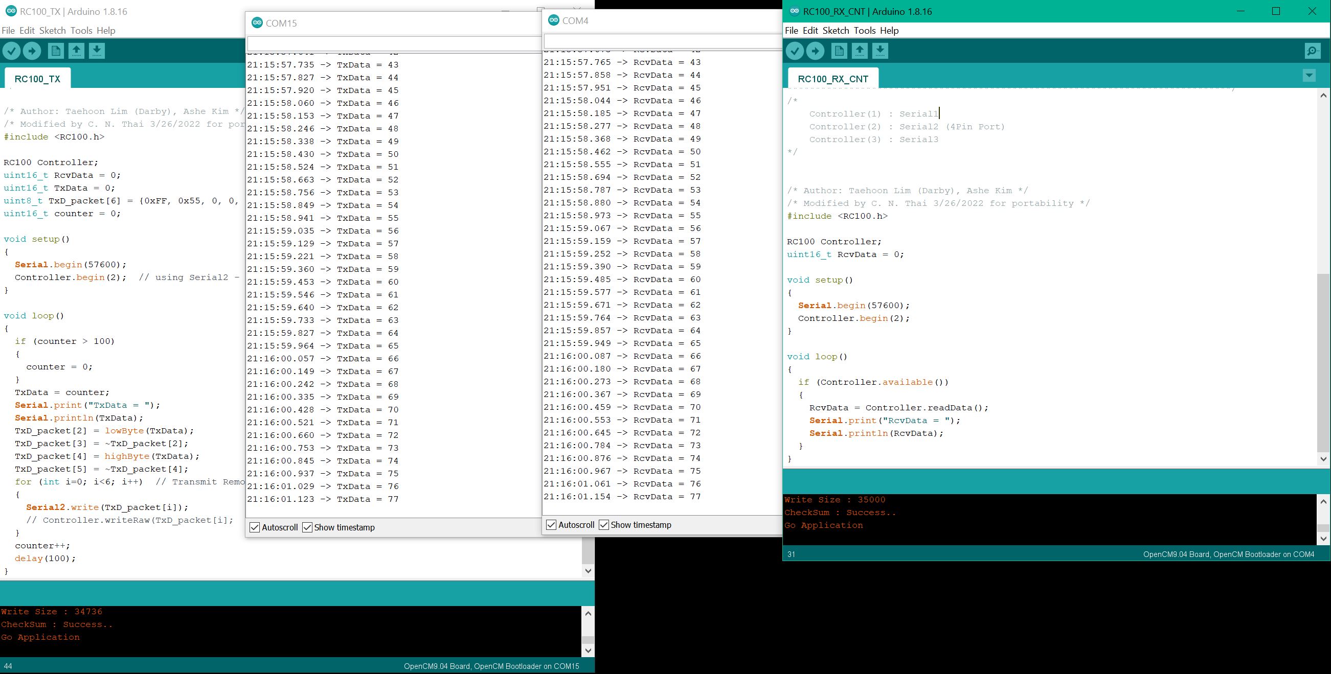
The listing of the sketch “RC_485_EXP_Serial_Protocol.ino” follows (note that it uses only “RC100.h” and “Dynamixel2Arduino.h”:

#include <RC100.h>
#include <Dynamixel2Arduino.h>

#define DXL_SERIAL_3 Serial3 //Serial3 is for DXL Port going to 485-EXP Board
#define DEBUG_SERIAL Serial
const uint8_t DXL_DIR_PIN_3 = 22; //“22” is DIR_PIN for 485-EXP Board
Dynamixel2Arduino dxl_3(DXL_SERIAL_3, DXL_DIR_PIN_3);

RC100 Controller;
uint16_t RcvData = 0;
uint32_t newGoalPosition = 0;
uint8_t id = 0;
uint32_t time_out = 100;

//This namespace is required to use Control table item names
using namespace ControlTableItem;

void setup() {
// put your setup code here, to run once:
Controller.begin(2);

int8_t found_dynamixel = 0;
// Use UART port of DYNAMIXEL Shield to debug.
DEBUG_SERIAL.begin(57600); //set debugging port baudrate to 57600 bps
while(!DEBUG_SERIAL); //Wait until the serial port is opened

dxl_3.begin(1000000); // need to match with DXLs baud rate used via Dynamixel Wizard

int8_t protocol = 2;
dxl_3.setPortProtocolVersion((float)protocol);
DEBUG_SERIAL.println("### SCANNING 485-EXP BOARD ");
DEBUG_SERIAL.print("SCAN PROTOCOL ");
DEBUG_SERIAL.println(protocol);
for(int id = 0; id < DXL_BROADCAST_ID; id++) {
//iterate until all ID in each baudrate is scanned.
if(dxl_3.ping(id)) {
DEBUG_SERIAL.print("ID : “);
DEBUG_SERIAL.print(id);
DEBUG_SERIAL.print(”, Model Number: ");
DEBUG_SERIAL.println(dxl_3.getModelNumber(id));
found_dynamixel++;
if (dxl_3.torqueOff(id))
DEBUG_SERIAL.println(“DYNAMIXEL Torque OFF”);
else
DEBUG_SERIAL.println(“Error: Torque OFF failed”);
if (dxl_3.setOperatingMode(id, (float) OP_POSITION)) // Position Control mode
DEBUG_SERIAL.println(“Position Control mode OK”);
else
DEBUG_SERIAL.println(“Error: Position Control mode failed”);
if (dxl_3.torqueOn(id))
DEBUG_SERIAL.println(“DYNAMIXEL Torque ON”);
else
DEBUG_SERIAL.println(“Error: Torque ON failed”);
}
}

DEBUG_SERIAL.print(“Total “);
DEBUG_SERIAL.print(found_dynamixel);
DEBUG_SERIAL.println(” DYNAMIXEL(s) found!”);
dxl_3.setGoalPosition(11, 2048); // Init Positions for DXL 11 and 12
dxl_3.setGoalPosition(12, 2048);
}

void loop() {
// put your main code here, to run repeatedly:
RcvData = 0;
if (Controller.available())
{
RcvData = Controller.readData();
}

if(RcvData == (RC100_BTN_U + RC100_BTN_1)) {
id = 11;
newGoalPosition = dxl_3.readControlTableItem(PRESENT_POSITION,id,time_out) + 50;
if (newGoalPosition <= 4095){
dxl_3.setGoalPosition(id, newGoalPosition);
delay(250);
}
else {
newGoalPosition = 4095;
}
}

if(RcvData == (RC100_BTN_D + RC100_BTN_1)) {
id = 11;
newGoalPosition = dxl_3.readControlTableItem(PRESENT_POSITION,id,time_out) - 50;
if (newGoalPosition >= 0){
dxl_3.setGoalPosition(id, newGoalPosition);
delay(250);
}
else {
newGoalPosition = 0;
}
}

I wrote the code as plainly as possible, so that you can adapt it in any way you want to.

Good luck on your project.

1 Like

Thanks for your suggestions. I will have a try by this weekend and let you know the results!

Thank you very much for sharing your experience. I will have a try soon based on your shared points and will let you know once I got some results!

Hi, thanks very much for your sharing. It seems I am on the same way and it has been proved correct. My previous code works well with my MX64-AR motors (using Dynamixel2Arduino). And what I did is integrate it with the RC-100 but it failed (communication well but no actuation). I will follow your way to debug my code and will update you as soon as possible!

Hi, thanks for correcting this. I did the corresponding correction but it still didn’t work (correct baud rate, ID, control mode etc). I will follow @roboteer 's sharing to modify my previous code and it would work hopefully.

Hi @roboteer @Yogurt_Man, thanks very much for your kind help and I solved this problem finally!!! :smiling_face_with_three_hearts: Now I can program the master controller and actuate the motors successfully. The main reason of my previous failure is when using the example code I mixed Dynamixel2Arduino and DynamixelSDK library, due to my short knowledge about how to play with RC100 and BT410 modules (I thought they can only work with DynamixelSDK instead of Dynamixel2Arduino). So the connection build but the motor can not understand well the command. :sweat_smile:

1 Like

Glad to be of help, and Yes I had found that mixing up libraries confuses and messes me up too, so I am using only “Dynamixel2Arduino” :smile:.

2 Likes